Velodrome Düren – UAS Surveying and Track Info Extraction

Table of Contents

Introduction

The “Jugendstadion” (Youth Stadium) in Düren-Rölsdorf, Germany was constructed in 1921, consisting of a football field and a wooden grandstand. Two years later, in 1923, a concrete velodrome was added to host stayer races where bikre racers compete against each other in the slipstream of motorcycles and reach speeds over 100km/h, which were very popular at the time.

Up until the 1980s, bike racing continued on the track until it fell into disrepair. Over the decades technical requirements for velodromes moved on, mandating specific bank angles, safety barriers and infield safety zones as well as a certain width of the track. For this project, the track is surveyed and the important characteristics of the track are calculated.

In order to assess the track, a survey is done using a DJI Mavic Mini. These products are created:

  • DSM (Digital Surface Model)
  • Orthophoto
  • Hillshade

From those products, the following information is extracted:

  • Banking angle of turns and straights
  • Track length and width
  • Turn radius
  • Inside safety zone width

Race at the Velodrome in Düren-Rölsdorf in 1968

UAV Surveying

Over 650 images were taken from heights ranging from 4m to 55m. It was specifically focused on the concrete race track to accurately depict its angle and position, while the grass in the middle was not photographed as intensively. The racetrack images were taken by flying both clock- and counterclockwise, with a camera angle of about 45° downwards.

Camera positions.

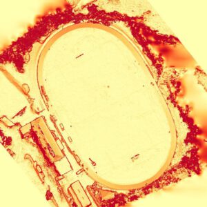
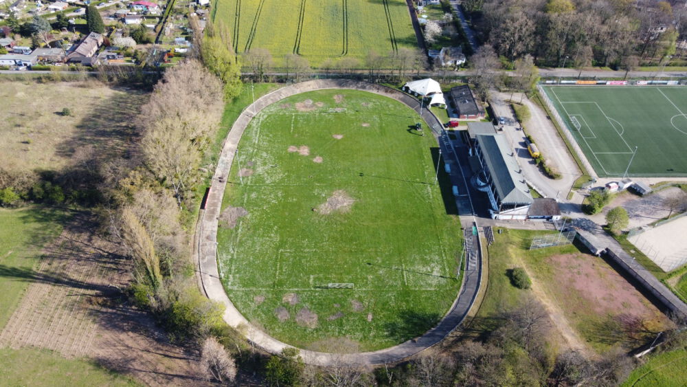
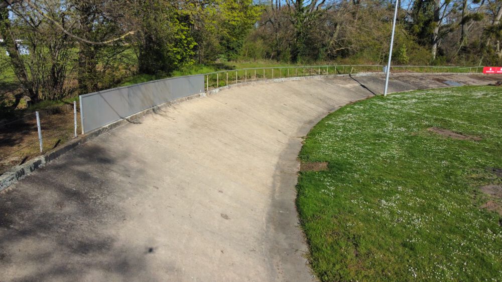
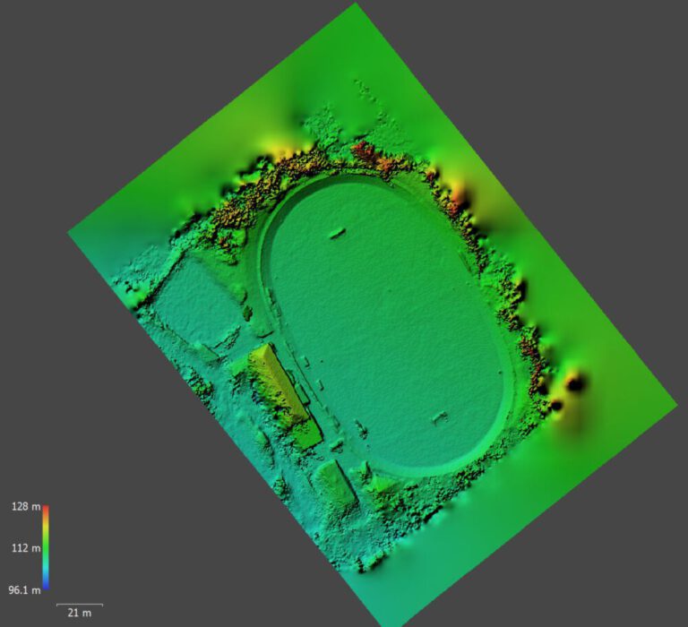
The dense cloud that has been calculated out of the aligned images consists of about 12 million points. The trees adjacent to the track create some disturbances, so the AOI will be adjusted to not extend much over the track limits.

Using the EXIF information embedded in the UAV images, the georeferencing was conducted (EPSG:4326). No GCPs were used for now, but 5 GCPs were measured and will be introduced to more accurately measure the DSM and the banking angle later. But for now, the X and Y absolute georeferencing is satisfactory, the Z referencing will be taken into account later.

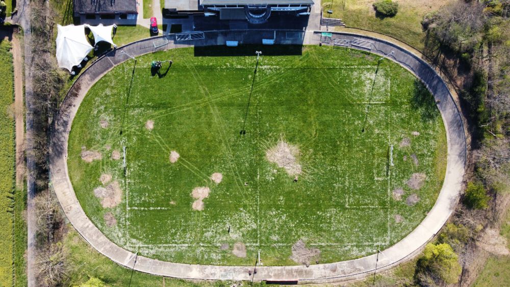
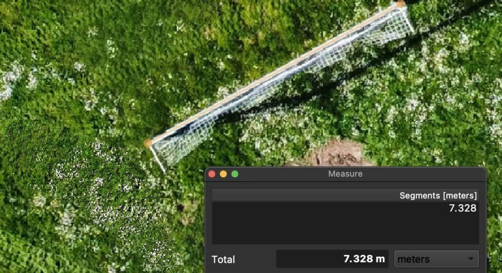
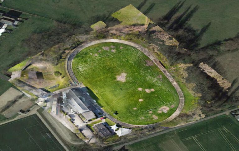
Just to demonstrate the relative accuracy, here is a measurement of an association football goal with a known length of 7.32m

Calculating the 3D dense point cloud with ≈12 million points took about 5 hours. The resulting point cloud is the basis for all next steps.

Digital Surface Model and Orthophoto

While the DSM will be the basis for the track banking angle estimation, the orthophoto is the basis for track length and width as well as the turn radius calculation. 

With a resolution (Ground Sampling Distance) of 8cm per pixel, the accuracy of the dense cloud layer (which is used to create those products) is more than enough. Since some alignment issues came up, the GSD varies quite a bite over the AOI but is never below 30cm per pixel.

Reprojecting the Orthophoto to WGS84 Web Mercator EPSG:3857 makes sure that a circle drawn on the orthophoto will be displayed  with the right angles and proportions.

DSM
Orthophoto

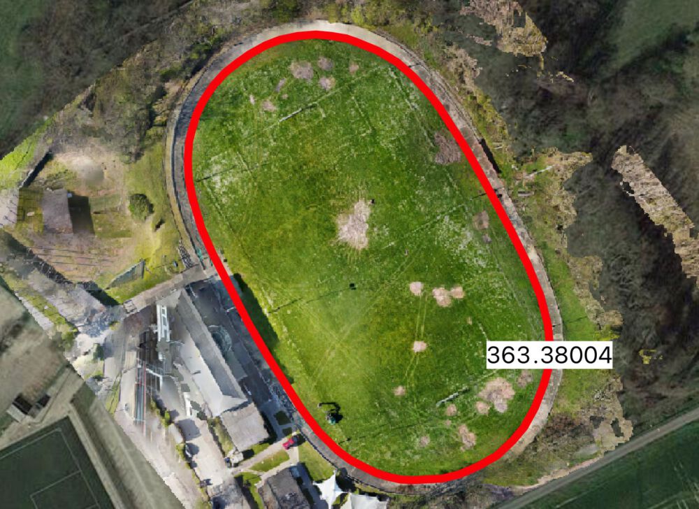
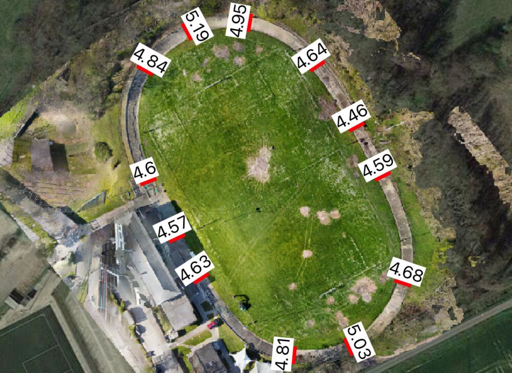
Track Length, Width, Safety Zone and Turn Radius

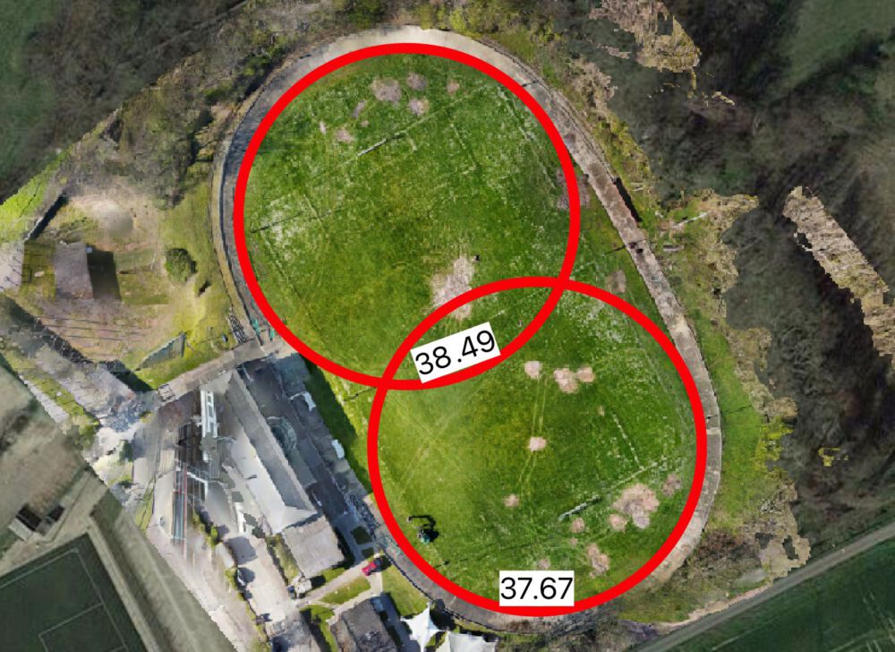
Using EPSG:3857 and QGIS, the length and width of the track are measured by creating line features and measuring their length via the QGIS field calculator. The turn radius is measured by creating circular features for both the north and south turns; and then calculating their radius according to their circumference by the well known formula that has been injected into the QGIS field calculator:

Track Length: 363.38m
Track Width: 4.5m (straights) - 5.5m (turns)
Turn Radius: 38.08m

Based on the aforementioned products and features, the following information has been extracted. Please note that the width is relative to the ground, the slope has to be accounted for aswell.

Info Value
Length 363.38m
Width (true to ground) 4.57m (Straight) -5.19m (Turn)
Turn Radius 38.08m

For safety reasons, a safety zone to the inside of a certain size is mandatory. Unfortunately, floodlights were constructed very close to the track.

2021-04-29 18_04_15-Fotos
Distance from track to floodlight post, measured in orthophoto.

Bank Angle

To find out the bank angle, a slope raster is calculated from the DSM.

Since taking sample points might not yield representative results, a line is drawn across the banking for both the turn and the straight. Along this line, the slope is extracted along the raster for each individuakl pixel.

Boxplot of slope at straight (in degrees).
Boxplot of slope at turn (in degrees).

The boxplots show that there is quite a lot of noise in the slope dataset, but the average should be a good representation of reality.

Sample points along turn and their slope values.
Slope visualization & mean slope along sampling lines.
Bank Angle at Straight 6.40°
Bank Angle at Turn 28.0°

Width

Using the angle and width of the track, the true angled width can be calculated.

Calculation of track width at straight.
Calculation of track width at turn.

Summary

Even though the accuracy of the 3D model and the orthophoto is not perfect, the values extracted should be very close to the real values. Issues arise mainly from the inconsistent growth of grass around the track, covering an unknown amount of track. The start- and endpoints of the length, width and safety zones therefore had to be estimated.
Lap Length 363.3m
Turn Radius 38.08m
Width 4.60m (Straight) - 6.24m (Turn)
Slope 6.40° (Straight) - 28.00° (Turn)
Safety Zone Width 1.0m

Based on todays standards for velodromes, the Jugenstadion in Rölsdorf is not useable for sanctioned racing events for the following reasons:

  • Track width insufficient: <7m
  • Safety zone insufficient: <3m
  • Track length not multipliable to 1000m using full or half laps
  • Poor concrete condition
  • Fence (ouside) not suitable 

2 Responses

  1. Hi Simon,
    You could use self-made GCPs derived from any aerial basemap in order to increase the location accuracy of your results. Of course, this method is still less accurate than the high res. GNSS receiver is but in my opinion, a really great and free solution to further improve the results.
    Finding already in situ artifacts in the scene is particularly easy in areas where you have artificial objects – like the stadium you analyzed.
    Besides that, I really like what you are doing, great job and keep going 🙂
    Best wishes,
    Bernd

    1. Thanks a lot for the feedback and the tip, I will definitely try that method next time!

Leave a Reply

Your email address will not be published. Required fields are marked *

Further Reading
Recent Updates